SystemVerilog from the beginning
The tutorial mainly focus on the SystemVerilog constructs and how could we use the language for both the “Design” and “Verification”. The concepts will be built from the scratch and are mainly discussed using sample designs. In the introduction we will give a quick introduction on the language basics and the discussion will be continued with a simple design.
“SystemVerilog is built on top of Verilog 2001. SystemVerilog improves the productivity, readability and reusability of Verilog based code. The language enhancements in SystemVerilog provides more concise hardware descriptions, while still providing an easy route with existing tools into current hardware implementation flows. The enhancements also provide extensive support for directed and constrained-random testbench development, coverage driven verification, and assertion based verification” the definition from SystemVerilog LRM(Extension to Verilog-2001).
Introduction
SystemVerilog is a Hardware Description Language(HDL). It is an extension to the most popular HDL Verilog. A major portion of SystemVerilog was released as an Accellera standard in June 2002 under the title of SystemVerilog 3.0. SystemVerilog mainly focuses on the “Verification” of designs. Although the designers could implement more complex designs such as processors, IPs and many more complex designs., the verification became a headache for the verification engineers. With the OOP(Object Oriented Programming) approach verification engineers got the ability of testing all the corner cases which they could not cover with other HDLs.
Simple Design
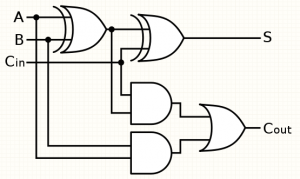
In this design we are mainly focusing on the one-bit simple adder.With the new concepts and ideas we will improve the design step by step.
The gate level design of one-bit full adder

Source : https://www.eeweb.com/quizzes/full-adder-nand-equivalent
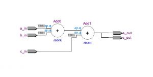
The behavioral design(SystemVerilog source code) of one-bit simple adder
1 2 3 4 5 6 7 8 9 10 11 12 13 14 | // simpleAdder.sv file module simpleAdder( input logic a_in, input logic b_in, input logic c_in, output logic s_out, output logic c_out ); always_comb begin {c_out,s_out}=a_in + b_in + c_in; end endmodule |
RTL synthesis from Quartus II 64-bit Version 13.0.1 Build 232 06/12/2013 SJ Web Edition

Note on the design
As in Verilog HDL, module simpleAdder(); with the input and output ports are used. Important thing to note is the “logic” variable type.
logic – a 1-bit 4-state variable, like the Verilog reg type.
always_comb is used instead of Verilog construct “always@(*). The always_comb block specifically synthesized to a combinational block.
More design constructs will be discussed with the designing of Testbench code for the one-bit simple adder.
For the further reference please refer the book “SystemVerilog for Design, 2nd Edition”, A Guide to Using SystemVerilog for Hardware Design and Modeling by Stuart Sutherland, Simon Davidmann and Peter Flake.

Leave a Reply