Verilog Gate Level Modeling
Gate Level Modeling describes a hardware circuit using the logic gates and their interconnections.
Verilog has become popular because it supports behavioral modeling where the user doesn’t have to worry about which logic gates needs to be used. In contrast, Gate level modeling requires you to take decisions on which gates need to be used.
Advantages
- Full control over which logic gates to be used in your design.
- Synthesized output doesn’t depend on the EDA tool used.
Disadvantages
- Difficult to use for complex circuits.
- Take more time to write the HDL code.
- Difficult to understand when the design is complex.
Example

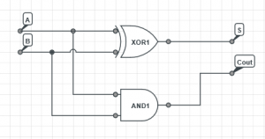
The above figure shows a 1-bit adder with carry out. A gate level model of that circuit is shown below.
2
3
4
5
6
7
8
9
input A,B;
output S,Cout;
and U1(Cout, A, B);
xor U2(S, A, B);
endmodule

Leave a Reply